- RSLINX CLASSIC LITE DRIVER CONFIGURE SERIAL
- RSLINX CLASSIC LITE DRIVER CONFIGURE DRIVERS
- RSLINX CLASSIC LITE DRIVER CONFIGURE DRIVER
RSLINX CLASSIC LITE DRIVER CONFIGURE SERIAL
Set to manual 2nd issue - is the enet to rs232 a good device to use for DF1 I use a Belkin USB to RS232 device, never used a ethernet to serial device.
RSLINX CLASSIC LITE DRIVER CONFIGURE DRIVERS
Right-click on F8 - FLOAT data file and select Properties.Ĭhange the number of elements to 8 and click on Apply. 1st go to RSLinx and set all your config drivers to manual, this is shown under the config display and the button is the startup button. Note that you are missing 7 FLOAT elements, 3 for inputs (F8:1. You must have, at least, as many elements as the ones defined in Factory I/O. Once a new project is created, one BINARY, OUTPUT, and FLOAT elements are already defined. Hover the mouse cursor over a grayed-out point to get relevant information about the error. When connected to a PLC, non-existent tags or tags with an error are grayed out.
RSLINX CLASSIC LITE DRIVER CONFIGURE DRIVER
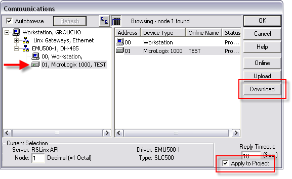
The SLC 500 (DH485) Emulator driver is chosen to download to RSEmulate500. Click on the arrow of Available Driver Types and select the driver. Now, click on CONNECT to connect to the PLC.Ī successful connection is indicated by a green icon next to the selected driver, as well as next to the driver's name displayed on the status bar. 1.Open RSLinx and click Configure Drivers of Communications menu. Press Esc to return to the Driver Window.


On this panel you can also define how many I/O Points to use, as well as what part of the controller's memory (tags) they reference.Įach I/O point (e.g. If you are using a 1400 model select 1400 from the Model list instead. Make sure 1100 Ethernet is selected in the Model drop-down list and insert the controller's IP address into the Host field. Open the driver Configuration Panel by clicking on CONFIGURATION. Select Allen-Bradley MicroLogix from the driver drop-down list. Configure Baud Rate, Data Bit, Stop Bits and Parity to match those in. Configure a serial comport using ADD Comport for the SCADA Node. RSLinx Classic, in all its variations (Lite, Gateway, OEM, etc.). RSLINX Lite does not support the C API and will not work with WebAccess. Using Rslinx Classic Configure Drivers Screen With A Configured Driver Chapter 4. In Factory I/O click on FILE > Driver Configuration to open the Driver Window. The WebAccess RSLINX driver uses the C Application Interface. You should now be able to find the controller under the newly added driver. Start RSLinx and open the driver configuration dialog by selecting Communications > Configure Drivers from the menu.

Which describes methods to assign an IP address to the controller.īy default, the controller is BOOTP enabled and will be assigned an IP address by a BOOTP server on the network. MicroLogix 1400 Programmable Controllers User Manual 1766-UM001, MicroLogix 1100 Programmable Controllers User Manual 1763-UM001 / To complete this step you should refer to the


 0 kommentar(er)
